
JTAG pin assignment for microcontrollers and FPGAs
JTAG needs four signals — TMS, TCK, TDI, TDO — plus reference voltage and ground. Depending on the tool, optional signals are added: reset, nTRST and RTCK for ARM, DONE, PROG or INIT for FPGA programmers.
6-pin — TC2030 and ECV3-06
| Contact | JTAG, 4-wire (FPGA) |
|---|---|
| 1 | VREF |
| 2 | TMS |
| 3 | TDI |
| 4 | TCK |
| 5 | GND |
| 6 | TDO |
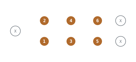
Plug-of-Nails™ TC2030 Series (example), view onto the PCB
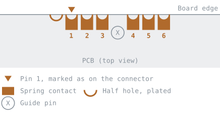
Edge-Connect™ ECV3-06, view onto the PCB
Matching cables and adapters: TC2030-ALT · TC2030-ALT-NL · TC-LATTICE
10-pin — TC2050 and ECV3-10
| Contact | ARM (Cortex-10) | JTAG generic | Xilinx | Lattice |
|---|---|---|---|---|
| 1 | VCC | VREF | VREF | VCC |
| 2 | TMS | TMS | TMS | TMS |
| 3 | GND | GND | GND | GND |
| 4 | TCK | TCK | TCK | TCK |
| 5 | GND, optional +5 V | not defined | GND | 5 V OUT (optional) |
| 6 | TDO | TDO | TDO | TDO |
| 7 | RTCK (optional) | RTCK (optional) | GND | DONE (optional) |
| 8 | TDI | TDI | TDI | TDI |
| 9 | nTRST (optional) | nTRST (optional) | PGND (optional) | TRST (optional) |
| 10 | nRESET (optional) | nRESET (optional) | HALT / INIT (optional) | ispEN / PROG (optional) |
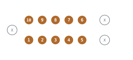
Plug-of-Nails™ TC2050 Series (example), view onto the PCB
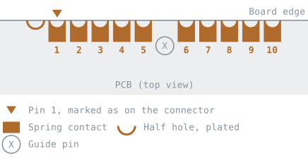
Edge-Connect™ ECV3-10, view onto the PCB
Matching cables and adapters: TC2050-ARM2010 · COLL-ARM20-10-IDC · TC2050-XILINX · TC-LATTICE-10
14-pin — TC2070 and ECV3-14
| Contact | JTAG (STDC14) |
|---|---|
| 1 | — |
| 2 | — |
| 3 | T_VCC |
| 4 | TMS |
| 5 | GND |
| 6 | TCK |
| 7 | GND |
| 8 | TDO |
| 9 | T_JRCLK (optional) |
| 10 | TDI |
| 11 | GNDDetect (optional) |
| 12 | T_NRST (optional) |
| 13 | — |
| 14 | — |
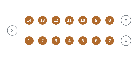
Plug-of-Nails™ TC2070 Series (example), view onto the PCB
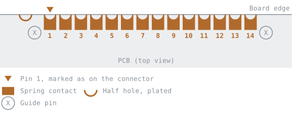
Edge-Connect™ ECV3-14, view onto the PCB
Matching cables and adapters: TC2070-IDC-050 · TC2070-IDC-NL-050 · ECV3-14-2AP-IDC-050 · COLL-ARM20-14P-050
For your own layout
- On 10 pins, the four JTAG signals sit on the same contacts for ARM, Xilinx and Lattice: TMS 2, TCK 4, TDO 6, TDI 8, supply 1, ground 3. Differences are limited to the optional signals on 5, 7, 9 and 10.
- If you lay out a board for several tools, populate the core contacts and decide the others by the tool actually in use.
- MSP430 uses an entirely different 10-pin assignment — see "Other assignments".
The position of the contacts is shown in Connector numbering.
All tables are derived from the pin assignments of the individual cables and adapters — manufacturer information, datasheets and our own measurements. For a specific cable, the table on its product page is authoritative.
All assignments at a glance: Pin assignments · SWD · UART · ST-LINK (STDC14) · Other assignments