
UART pin assignment of the Tag-Connect footprints
For the serial interface (UART) there are two fixed assignments: six pins with handshake lines, as carried by the FTDI cables, and the virtual COM port (VCP) on the 14-pin STDC14 connector of the ST-LINK V3.
6-pin — TC2030 and ECV3-06
| Contact | UART |
|---|---|
| 1 | VCC |
| 2 | CTS (optional) |
| 3 | RxD |
| 4 | TxD |
| 5 | GND |
| 6 | RTS (optional) |
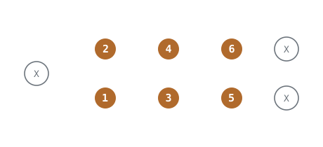
Plug-of-Nails™ TC2030 Series (example), view onto the PCB
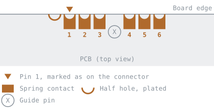
Edge-Connect™ ECV3-06, view onto the PCB
Matching cables and adapters: TC2030-FTDI-TTL-232R-3V3 · TC2030-FTDI-TTL-232RG-VIP · COLL-FTDI-232R-06-14P
14-pin — TC2070 and ECV3-14
| Contact | VCP (STDC14) |
|---|---|
| 13 | T_VCP_RX |
| 14 | T_VCP_TX |
| 5, 7 | GND |
| 3 | T_VCC |
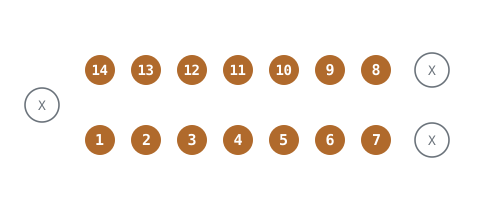
Plug-of-Nails™ TC2070 Series (example), view onto the PCB
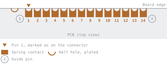
Edge-Connect™ ECV3-14, view onto the PCB
Matching cables and adapters: TC2070-IDC-050 · TC2070-IDC-NL-050 · ECV3-14-2AP-IDC-050
For your own layout
- On 6 pins, UART uses the same contacts as 4-wire JTAG: RxD on TDI (3), TxD on TCK (4), CTS on TMS (2), RTS on TDO (6). The FTDI cables label their wires accordingly.
- RxD and TxD are named from the cable's or adapter's point of view. They cross on the target board: the cable's TxD line goes to the controller's RX input.
- Contact 1 differs in direction depending on the cable — supply from the cable or reference voltage from the target. Check the product page before connecting for the first time.
- There is no fixed UART assignment on 10 pins.
The position of the contacts is shown in Connector numbering.
All tables are derived from the pin assignments of the individual cables and adapters — manufacturer information, datasheets and our own measurements. For a specific cable, the table on its product page is authoritative.
All assignments at a glance: Pin assignments · SWD · JTAG · ST-LINK (STDC14) · Other assignments